48I-VDC &220I-VDC i-modular parallel inverter ngaphandle kwebhethri elicwengekile se-Sine Wave Inverter 3KW inverter

19 Inch 110VDC & 220I-VDC Parallel Inverter Manual Manual Parallel Inverter Supply

I-DC 48V 10000 I-Watt Inverter 10KVA Pure Wave Sine Power Inverter Telecom 4U rack Mount inverter

Isistimu yamandla eshumekiwe 3U DC 48V 150a Ukushintsha Amandla Amandla

I-BWITT-Phase BWITT 48V kuya ku-AC220V 1000w Pure Sine Wave Inverter 1000w Inverter ne-SNMP


The working principle of the inverter is to control the operation of the entire system through a control circuit. The inverter circuit completes the function of converting direct current to alternating current, and the filter circuit is used to filter out unwanted signals.
The work of the inverter circuit can also be refined as follows: first, the oscillating circuit converts direct current into alternating current; secondly, the coil boosts the irregular alternating current into square wave alternating current; finally, rectification makes the alternating current into a sine wave alternating current through a square wave.
The working principle of each part of the inverter
1. Input interface part: Ingxenye yokufaka inayo 3 amasiginali, 12V DC OPPT VIN VIN, Ukusebenza Kunika amandla i-Voltage Enb nePaneli Control Signal. I-VIN ihlinzekwa nge-adaptha, kanye ne-Enb Voltage ihlinzekwa yi-MCU ebhodini lomama, and its value is 0 noma i-3V. Lapho Enb = 0, I-inverter ayisebenzi, Futhi lapho enb = 3V, the inverter is in normal working state; while the DIM voltage Provided by the main board, the range of variation is between 0-5V. Different DIM values are fed back to the feedback terminal of the PWM controller. Okwamanje kuhlinzekwe yi-inverter emthanjeni nakho kuzohluka. Incane inani elifiphele, the current output by the inverter. Omkhulu.
2. Voltage start circuit: When ENB is at high level, it outputs high voltage to light the panel's backlight tube.
3. Isilawuli se-PWM: Inemisebenzi elandelayo: I-Internal Reference Voltage, Iphutha Amplifier, oscillator no-pwm, Ukuvikelwa kwe-voltage ngaphezulu, Ukuvikelwa kwamandla kagesi ngaphansi, Ukuvikelwa okufushane kwesizungu, output transistor.
4. Ukuguqulwa kwe-DC: The voltage conversion circuit is composed of MOS switch tube and energy storage inductor. The input pulse is amplified by the push-pull amplifier and then drives the MOS tube to switch, so that the DC voltage can charge and discharge the inductor, so that the other end of the inductor can be Obtain AC voltage.
5. I-LC Oscillation kanye ne-Output Circuit: to ensure the 1600V voltage required for the lamp to start, and to reduce the voltage to 800V after the lamp is started.
6. Impendulo yeVoltage Volput: Lapho umthwalo usebenza, the sampled voltage is fed back to stabilize the voltage output of the inverter
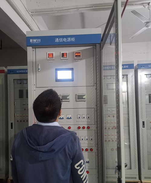
I-BWITT ingumhlinzeki oholayo emhlabeni wama-telecom we-telecom afakwe ku-rack.
I-inQury9 / E f, Ukwakha ipaki yezimboni ezingama-20 ze-Ericsson, -Nokuba. 19, I-Huifeng East 1st Road Zhongkai High-Tech Zone, I-Huizhou City Guangdong Province China